The shop table has come a long way since its humble beginnings. The whole process has taken place on the workbench. However, today is the day the carcass officially becomes a cabinet and can no longer reside on the much needed real estate of the workbench.
 So here it is. On the shop floor. Upside down. "Upside down?" you ask. Yes. It's in its current orientation because today we'll working on the base.
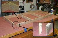
 Here are the parts for the base. I would normally design for a 3-1/2" to 4" tall base for toe space, however, in order to accommodate for the larger tools that will be stored in the cabinet, something had to give. The inset pictures show the corner joint, which is a miter reinforced with a #10 biscuit and the intermediate connection, which is pocket screws. If you look close in the picture, you can also see the pocket screw holes that will be used to attach the base to the cabinet.
 After assembly of the base, it's centered on the cabinet bottom and attached with pocket screws, as mentioned above. This completes the basics, now it's time for the accessories. The cabinet will receive casters to make it easier to move around, should the need arise. However, I don't want this thing rolling all around while I'm trying to work. So we'll add some pads for the table to sit on, lifting it just enough to get the casters off the floor. I call these pads lifters and we'll talk more about those later.
 Since the cabinet will be supported by the lifters at each end, I want to add some reinforcement as well as make the bearing surface a little wider. This is simply done by adding a strip of 3/4" plywood with some glue and brads.
 Next, it's time to get started adding the casters. I will be using 1/4"x1" lag screws, which unfortunately, are 1/4" too long for the 3/4" plywood bottom. This wouldn't normally be a problem, but I don't want the protrusion on the inside of the cabinet to affect the sliding-out of the slide-out shelves. So, we'll add some shims made of 1/4" hardboard at the locations of the casters.
 Once the hole locations for the mounting plate on the casters are marked, I drill 11/64" holes then set the caster in position and drive the lag screws home. (After looking at the picture, one might wonder how this thing is supposed to roll with the wheels going all ev'ry-which-a-way. I may have neglected to the mention that these are swivel casters. Sorry for any confusion.)
 Here are the lifters I spoke of earlier. They are two pieces of 3/4" plywood, glued and a screwed. They are about 2" wide, which is plenty of bearing surface.
 And here's the cabinet, up-right and sitting on its lifters. By the next posting, I'll have the drawer slides in. This should go pretty easy since I've already drilled the holes for the slides when this thing was on the workbench. After the slides are in, we can start making drawers....fun, fun.
No comments:
Post a Comment